
 with intrusion detection capability based on software-defined networking (SDN) and Machine Learning techniques")
This section details the SRAIOT to improve communication security in the IoT structure. In SRAIOT, SDN creates a secure communication platform between network things. In this case, the network structure is divided into a set of subnets. The members of each subnet will be highly similar in terms of position and movement pattern, and this guarantees the stability of network topology communication. Also, in this structure, the task of authenticating and managing the communication of the members of each subnet is assigned to a controller node. In addition to this communication structure, a neural network based learning model is used to monitor network traffic. In this way, each controller node uses this learning model to identify attacks and security threats in its subnet. The assumptions used in SRAIOT are as follows:
-
Due to the different technologies for making radio equipment in wireless networks, network nodes have non-homogeneous communication characteristics. As a result, the assumed network is inhomogeneous.
-
The assumed network structure is designed based on the 5G network technology; Therefore, it has all the characteristics and requirements of this communication technology.
-
The distance between two nodes can be calculated by estimating the strength of the radio signal received by each node. Therefore, if the network equipment does not have a global positioning system (GPS), they can estimate the distance to each other by checking the received signal strength of the adjacent nodes.
-
Each controller node in the SDN is equipped with a learning model that can record and process data traffic. This learning model is an artificial neural network; It is used to identify attacks and security threats in the subnet corresponding to the controller node.
SRAIOT to improve communication security in the structure of IoT based on SDN and EL includes the following steps:
-
1.
Formation of network clustering structure based on SDN
-
2.
Formation of network hierarchical tree topology
-
3.
Data routing using a formed structure
-
4.
Detection of attacks based on EL
The details of SRAIOT steps are shown as a diagram in Fig. 1. As seen in this figure; SRAIOT is repeated in specific time intervals such as Ît. In the first step of SRAIOT, the SDN domain is divided into several subdomains using a clustering solution based on the movement pattern of active nodes, and each part is equipped with a controller to exchange security rules with other subdomains.
In SRAIOT, each controller will provide the list of authenticated users related to its subdomain to other controllers. In this way, if there is a need to establish communication between two users, the user’s credit is done by exchanging messages between the controllers. If each of the two sides of the communication is authenticated by at least one controller, the data routing will be done.
To control the network topology, the minimum spanning tree and Prim algorithm are used. In this step, each node forms the topology of the network locally through the construction of minimum-spanning trees. Then, by leveling network nodes and determining the weight of network connections, a hierarchical tree is formed for data routing. Finally, the data is routed to the destination through the hierarchical tree structure. Based on the structure proposed in this research, all the traffic of nodes related to a subnet is exchanged through the controller node of that subnet. Therefore, each controller node continuously uses an EL learning model to analyze network traffic information and identify attacks. This model is composed of three learning models and, based on the statistical information extracted from each traffic flow, identifies the possible presence of attacks in it. Each of these steps is explained in the following.
Formation of network clustering structure based on SDN
In the first step of SRAIOT, a topology structure will be created to determine the secure communication infrastructure between network things. For this purpose, it is necessary to first identify the list of neighbors of each active node in the network, which is done by exchanging Hello control packets. In this process, each node stores its unique identifier in the content of the control packet, and then by broadcasting this message, it informs its existence to the neighboring nodes. Each active node, upon receiving this message, will add the ID of the sending node to its neighbors list. During these exchanges, the signal strength received from each adjacent node is also measured and recorded by the node. By repeating this process, each active node will produce a list containing the ID of its neighbors as well as the strength of the signal received from them.
In the next step, the network nodes exchange their neighbors lists so that the low-quality network connections are identified and removed. For this purpose, each active node will send the received signal strength from neighboring nodes to them. The received signal strength of node B is shown by node A as RSSIA,B. By exchanging the signal strength values, each of the nodes A and B will be informed of the signal strength level received by the other node. In such a situation, a node like A evaluates the quality of its connection with node B based on the following conditions:
-
Having the strength of the received signal in the connection between A and B, active node A calculates the average signal power of both sides of the connection \({R}_{AVG}=\frac{RSS{I}_{AB}+RSS{I}_{BA}}{2}\). With this method, the destructive effect of noise in signal evaluation can be reduced to some extent.
-
If the average signal strength, \({R}_{AVG}\), is greater than the threshold, P, then the connection between two nodes A and B has sufficient quality and will be considered as an active connection. Otherwise, the connection between the two nodes will be ignored.
-
If the connection between A and B does not have the required quality, then the active nodes A and B remove each other from the list of their neighbors.
Implementing this process by each network node establishes a set of communication links with appropriate quality between the active network nodes. Each active node in the network will send its characteristics including ID, position information, and radio range to the active nodes located in its neighborhood using a control packet. Upon receipt of the topology construction control packet by each neighboring node, this information is sent to the neighbor with the highest degree of neighborliness (the node with the highest number of connections). If this process is repeated, the topology construction control packets are sent to the node with the highest degree of neighborhood. This node is called the central node Ct. After receiving all control packets of the topology construction by the central node, a view of the communication pattern of the network nodes will be created by the central node and this node will be able to create the graph of network active nodes. The central node, by using the positional information received from the active nodes, calculates the stability of the connection between both active nodes, such as i and j, as follows29:
$${T}_{ij}= \frac{d.\mathrm{cos}({\varphi }_{ij})+ \sqrt{{r}^{2}-{d}^{2}{\mathrm{sin}}^{2}({\varphi }_{ij})}]}{{v}_{ij}}$$
(1)
$${v}_{ij}=\sqrt{{\left({v}_{i}\mathrm{cos}\left({\varphi }_{i}\right)-{v}_{j}\mathrm{cos}\left({\varphi }_{j}\right)\right)}^{2}+{\left({v}_{i}\mathrm{sin}\left({\varphi }_{i}\right)-{v}_{j}\mathrm{sin}\left({\varphi }_{j}\right)\right)}^{2}}$$
$${\varphi }_{ij}={\mathrm{tan}}^{-1}\frac{{v}_{i}\mathrm{sin}\left({\varphi }_{i}\right)-{v}_{j}\mathrm{sin}\left({\varphi }_{j}\right)}{{v}_{i}\mathrm{cos}\left({\varphi }_{i}\right)-{v}_{j}\mathrm{cos}\left({\varphi }_{j}\right)}$$
In (1), \({v}_{i}\) represents the movement speed of node i, and \({\varphi }_{i}\) specifies the movement angle of this node. Also, r represents the radio range of the node and d represents the distance between two nodes i and j, estimated by sampling the received signal strength. By using the above relations, it is possible to predict whether two nodes i and j will be neighbors after the time interval \(\Delta t\) or not. This will happen if \({T}_{neighbor}\ge \Delta t\).
By calculating the value of \({T}_{ij}\) for each pair of nodes in the network, a similarity matrix is formed. This matrix contains the movement patterns similarity degree of both pairs of nodes. All the nodes send their estimated communication stability value to the central node Ct so that the topology construction is done. To construct the network topology, the central node integrates the received \({T}_{ij}\) values and categorizes the nodes into clusters using two basic rules. In this method, the nodes that have the same movement pattern are placed in a cluster. To detect the similarity of the movement pattern of two nodes, the following conditions are checked:
-
Two nodes should be in the same radio range (both nodes have one-step and direct access to each other)
-
It should be predicted that after a period of time \(\Delta t\), the distance between two nodes does not exceed the minimum radio range of two nodes.
For the second condition, the method of predicting the position and durability of the connection between two nodes is used (1), and based on these criteria, the information of the movement pattern of users is stored in a matrix like T. The clustering of network nodes is done based on this matrix. Using these two rules, the steps of clustering nodes in the network are as follows:
|
Input:â<âuser list L, connection period matrix Tâ>â |
|---|
|
Output: network clusters C |
|
1. Repeat the following steps until a node is in the list L |
|
2. Pick a random node like x in list L and remove it from L and create a new cluster in C |
|
3. For each node like \(y\in L\): if y is a neighbor of x and based on the matrix T, and \({T}_{xy}\ge \Delta t\) then add y to the current cluster in clustering C and omit node y from the list L |
|
4. If Lâ=âÏ, terminate the algorithm otherwise go to step 1 |
After doing these steps, all network nodes are placed in clusters according to their movement pattern. The next step of SRAIOT is to select the cluster head as the SDN controller. For this purpose, the node that has the highest degree of neighborhood in each cluster is determined as the head of the cluster and the SDN controller. Then, each cluster member node in the network has a direct connection only with its SDN controller (it will not even connect with its neighbors). The goal is to require network users to be authenticated through the SDN controller in order to avoid security risks inside or outside the clusters. Also, by using this structure, each node is required to exchange its traffic with others through the controller node, and thus, it will be possible to monitor this information and detect attacks using the learning model for all information exchanged in the network. After determining the SDN controller as the cluster head, each controller will find the shortest path to the central node Ct through intermediate nodes (which will act as cluster gateways). This process is explained below.
Formation of network hierarchical tree topology
In this step, the clustered structure of the network in the previous step will be transformed into a hierarchical structure. For this purpose, construction of a hierarchical topology begins with the use of a controller node as a central one. This central node is considered as the root of the hierarchical tree. Therefore, the first step in constructing a hierarchical tree topology is to determine a node as the central node of the network topology. The feature of neighborhood degree can be a suitable feature to determine the topology center. In SRAIOT, first the controller nodes determined in the previous step identify their neighbors by broadcasting all the control packets. Each network node waits for a short time after redistributing the topology construction packet to receive all response packets. Then it informs the neighbors about the number of neighbors by sending multicast packets. By repeating this process, the controller with the largest number of neighbors in the network will be defined and this controller node will be determined as the topology center. During this process, each responding node stores the control message, its information: congestion, energy, and estimated distance in the response packet and sends it to the sender node. This information will be used to weight network connections so that a hierarchical topology with the most suitable features can be produced. The proposed algorithm, based on the information of congestion, distance, and energy of the node, weights the network connections to construct the most suitable hierarchical tree.
In SRAIOT, considering the congestion degree parameter in addition to node energy, the weight of network connections is determined. The purpose of constructing a hierarchical tree based on these weighted connections is to avoid sending data to nodes that are in a congested state and also to provide the possibility of using nodes with higher energy and lower degree of congestion. The formula for calculating the weight of each connection to node i in SRAIOT is as follows:
$${W}_{ij}=\left(\frac{{C}_{j} \times {D}_{j}}{{E}_{j}}\right)$$
(2)
where Cj is the degree of congestion of child node j, which is calculated by (3).
$${C}_{i}=\frac{{T}_{service}}{{T}_{arrival}}$$
(3)
Also, \({D}_{j}\) is the estimated distance between the current node and neighboring node j, and \({E}_{j}\) represents the remaining energy of node j. Each node responding to the control message puts the above parameters on its ACK packets and sends them to the sender node. Also, all the values of \({C}_{j}\), \({D}_{j}\), and \({E}_{j}\) parameters are normalized by following equation before using in (2).
$${N}_{i}=\frac{{n}_{i}-{n}_{min}}{{n}_{max}- {n}_{min}}$$
(4)
As mentioned, the advantage of using this method is to prevent congestion in a node by choosing routes with less congestion and more energy. After determining the weight of all connections by (2), a hierarchical tree structure will be constructed.
After determining the weight of network connections, the central controller node will have the weight of all connections and the list of all network clusters. The shortest paths between the central node and other network clusters construct the hierarchical tree structure. In this way, each controller node (cluster manager) finds the shortest path (the path with the lowest total connection weight) to the central node through intermediate nodes (which act as cluster gateways). In this way, the clustering structure of the network will be transformed into a hierarchical tree topology, which will be used for the secure data routing process in the time period \(\Delta t\).
Data routing using the constructed structure
After constructing the hierarchical tree topology, this structure will be used for secure data routing. According to the tree topology, it is clear that there is only one path between both subdomains. However, for secure data routing between mobile nodes in the network, the controllers of each subdomain must exchange their members’ information. In this way, if a node intends to send data to another node, the source node first sends the ID of the destination node to its subdomain controller. If the destination node is located in the same subdomain, the connection between the two nodes is done by sending a response message to the source node. Otherwise, the controller node sends the message sent from the source to the central controller Ct. After receiving this message, Ct sends packets containing the ID of the destination node to the controllers of other subdomains. The controller that has the destination node in its subdomain sends a confirmation message to the source node through the central node Ct. In this way, the connection between the two nodes will be established. An example of the routing process in the proposed algorithm is shown in Fig. 2. To keep the simplicity, in this figure, the communications between the gateway nodes are not considered.

An example of the data routing process in SRAIOT.
In Fig. 2, it is assumed that a node like A in subdomain 1 intends to connect to node B in subdomain 3. In this case, node A first sends a message containing the ID of the destination node to controller C1. Considering that node B is not in the sub-domain of C1, so this controller sends the received packet to controller Ct. This controller also sends this message to other controllers (C2 and C3). Considering that destination node B is located in the subdomain corresponding to node C3, a response packet is sent by this subdomain to the source node. In the end, the data packet is exchanged between two nodes through the discovered path. During data routing by the controller nodes, the process of traffic information analysis and intrusion detection is done using EL. In the following, the structure of the proposed learning model is explained.
Intrusion detection in each subnet based on EL
As mentioned, each controller node in the software-based network is equipped with an EL model that can record and process the flowing data traffic by itself. This learning model, which actually consists of three learning models: âartificial neural networkâ, âK nearest neighborâ and âsupport vector machineâ; is used to identify attacks and security threats in the subnet corresponding to the controller node. In order to reduce the complexity and computational load imposed on the controller nodes, the learning model deployed in these nodes will only analyze the traffic sent from its sub-network nodes. so, it is possible to prevent network equipment and routers from infecting with malicious codes at the beginning of the sending process, and the malicious node can be easily identified. This process is illustrated with an example in Fig. 3.

The performance of controller nodes to identify attacks based on EL.
To maintain simplicity, it is assumed in Fig. 3 that two nodes are located in the same subnet. Node A sends malicious messages and node B is normal. It is assumed that each of these nodes intends to send a message to the other. As mentioned, all network nodes exchange data through their subnet controller, and this controller checks all the messages sent by the subnet members by a neural network model. In the scenario of Fig. 3, when node A sends a malicious message to the controller, before any processing, the characteristics of the package are extracted and classified by the artificial neural network. If the artificial neural network places the received message in the category of attacks; The message will be blocked and deleted. This condition occurred for the hypothetical sending message from node A to node B. On the other hand, the message sent by node B is detected as normal by the neural network located in the controller, and therefore it is sent to the receiver node A. In the following, the process of detecting attacks based on artificial neural network is explained.
The first step in the process of detecting attacks is the standardization of packet traffic information. To standardize the data, the following actions are performed:
-
The nominal characteristics of the traffic flow being processed are numerically valued. For example, the “connection type” attribute can have one of ICMP, UDP, and TCP states, and these values are replaced by numbers one to three.
-
The numerical characteristics obtained for the traffic flow are normalized using (4).
After normalizing the traffic flow features, the combination of “artificial neural network”, “K nearest neighbor” and “support vector machine” is used to detect attacks through the obtained features. Each of the mentioned learning models is trained independently and using training samples. Then the test samples (network traffic features) are processed by each of these learning models and the output of each model is defined as a logical variable. In this case, the True output for each learning model means there is an attack, and the False output means that the data flowing in the network is normal. After determining the output of the three learning models used in the proposed aggregate system, the voting technique is used to determine the result of intrusion detection. In this case, each test sample will belong to the output class whose label corresponding to that class has the highest vote among the learning models. In other words, the proposed aggregate system will recognize a traffic flow as an attack if at least two learning models in this system detect the characteristics of that traffic flow as an intrusion.
The remainder of this section describes the characteristics of the classifications used in the proposed aggregate system.
K nearest neighbor
The K-nearest neighbor method is one of the simplest machine learning algorithms for classification purposes. In this algorithm, a sample is classified by the majority vote of its neighbors and this sample is determined in the most general class among k nearest neighbors. The k-nearest neighbor method is used for many methods because it is effective, non-parametric, and easy to implement. For this reason, in SRAIOT, it is considered as one of the aggregate model algorithms. This algorithm classifies a test sample based on k nearest neighbors. The training samples are represented as vectors in the multidimensional feature space. The space is partitioned into regions with training samples. A point in the space belongs to a class that has the most training points belonging to that class within the closest training sample to k in it30. In SRAIOT, the Euclidean distance criterion is used in the KNN model. Also, the parameter K or the number of nearest neighbors is set equal to 5.
Support vector machine
The second learning model used in the proposed aggregate system is the support vector machine. Algorithms based on support vector machines are algorithms that try to maximize a margin. To find the categories separating line, these algorithms start from two parallel lines and move these lines in opposite directions so that each line reaches a sample of a specific category on its side. After this step, a strip or border is formed between two parallel lines. The greater the width of this band, it means that the algorithm was able to maximize the margin and the goal is to maximize the margin31. The shape of the boundary between the plates separating categories is determined through the kernel function of the support vector machine. In SRAIOT the linear kernel function is used to detect attacks in each subnet.
Artificial neural network
This neural network is a perceptron network with a hidden layer. The hidden layer of this network has 10 neurons and its transfer function is defined as logarithmic sigmoid. Also, the number of neurons in the input layer is equal to the number of features of the traffic flow, and the number of neurons in the output layer is 2. The output value of this neuron indicates the existence of an attack in the network. The structure of this network is shown in Fig. 4. LevenbergâMarquardt backpropagation algorithm32 is used to train the neural network. This algorithm performs network learning by bringing the output error closer to zero and based on the Jacobi matrix.
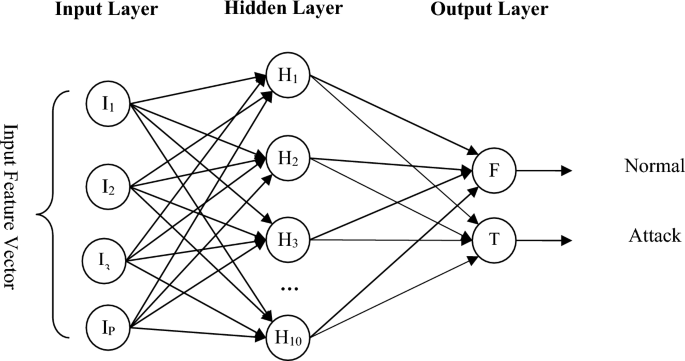
Neural network structure for detecting the presence of attacks in each controller node.
As mentioned, after determining the output of each of the above three learning models in the controller node, voting is done between the outputs and the result of attack detection is based on the result of the majority vote.

Tyler Fields is your internet guru, delving into the latest trends, developments, and issues shaping the online world. With a focus on internet culture, cybersecurity, and emerging technologies, Tyler keeps readers informed about the dynamic landscape of the internet and its impact on our digital lives.